01 / FIT + TOLERANCE
Allow for the real room.
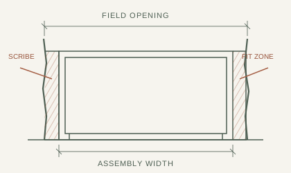
Plan scribe zones, shim space and adjustment allowances around field measurements and finish buildup. Define the fit at adjoining surfaces to reduce on-site cutting and rework.

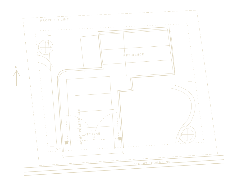
From the driveway approach to the hinge connection: document the conditions, coordinate the interfaces and turn design intent into measured fabrication drawings.
SITE + CONNECTION
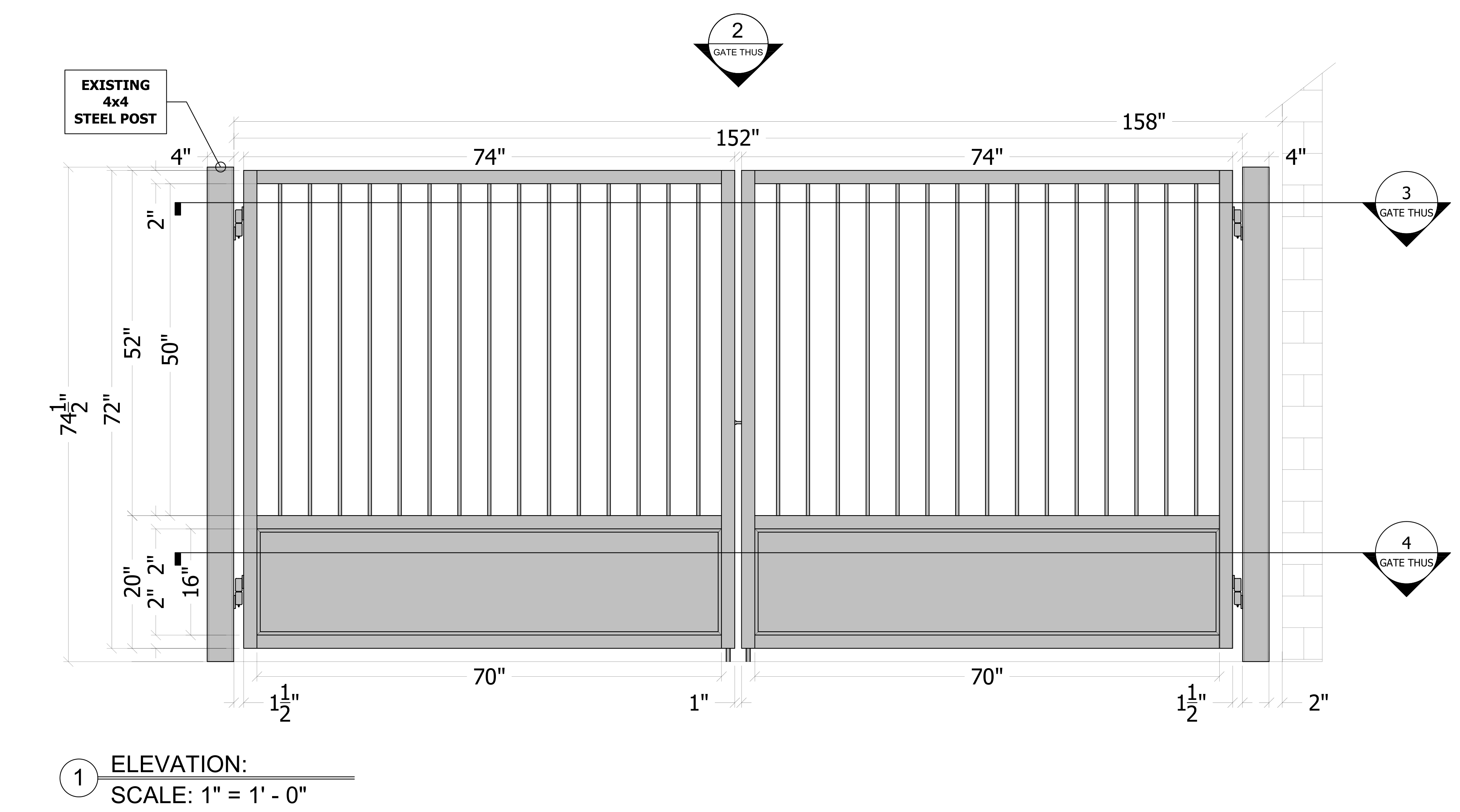
Residential drive study beneath original gate fabrication details.
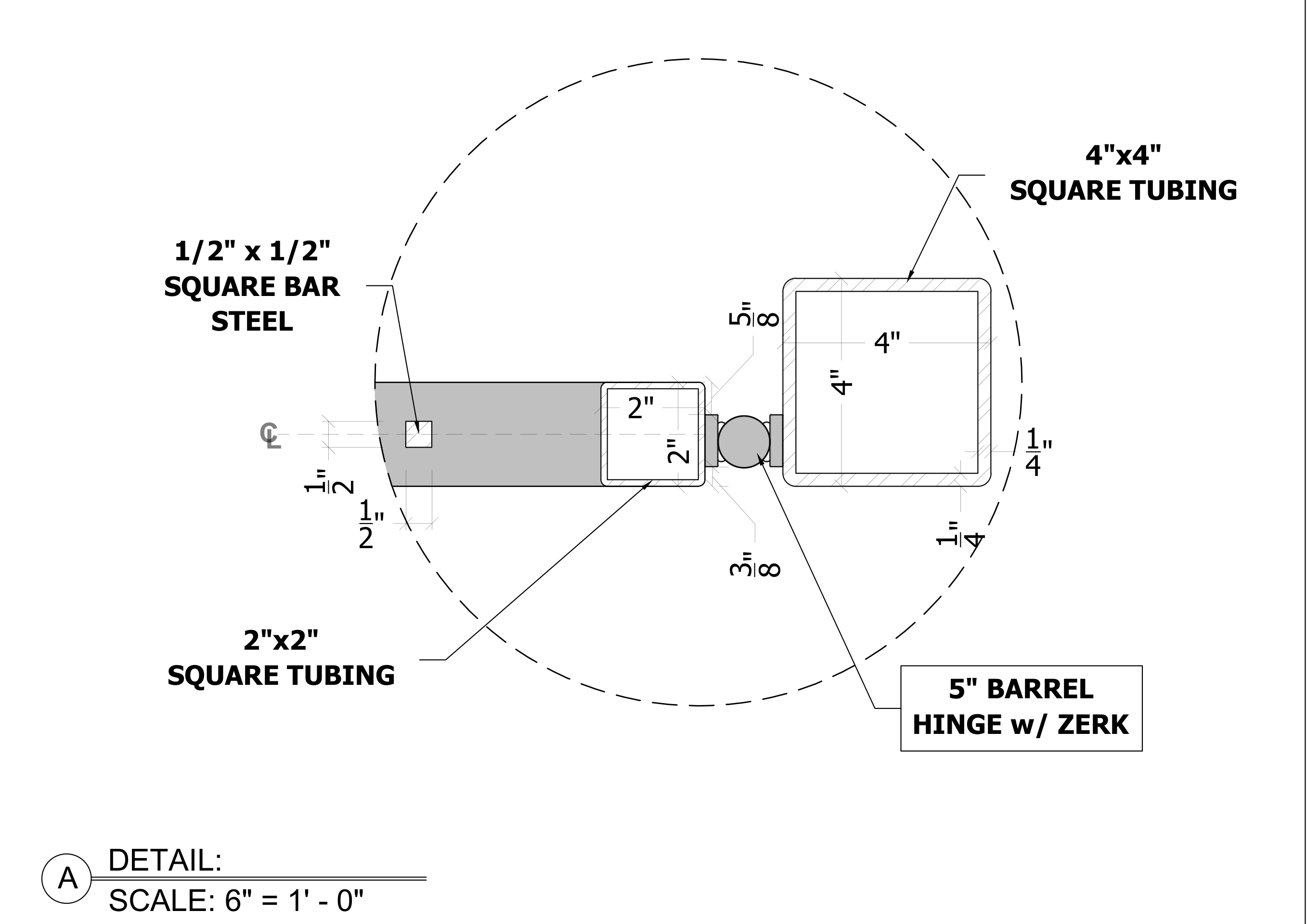
Selected drawing details, takeoff studies and coordination notes.
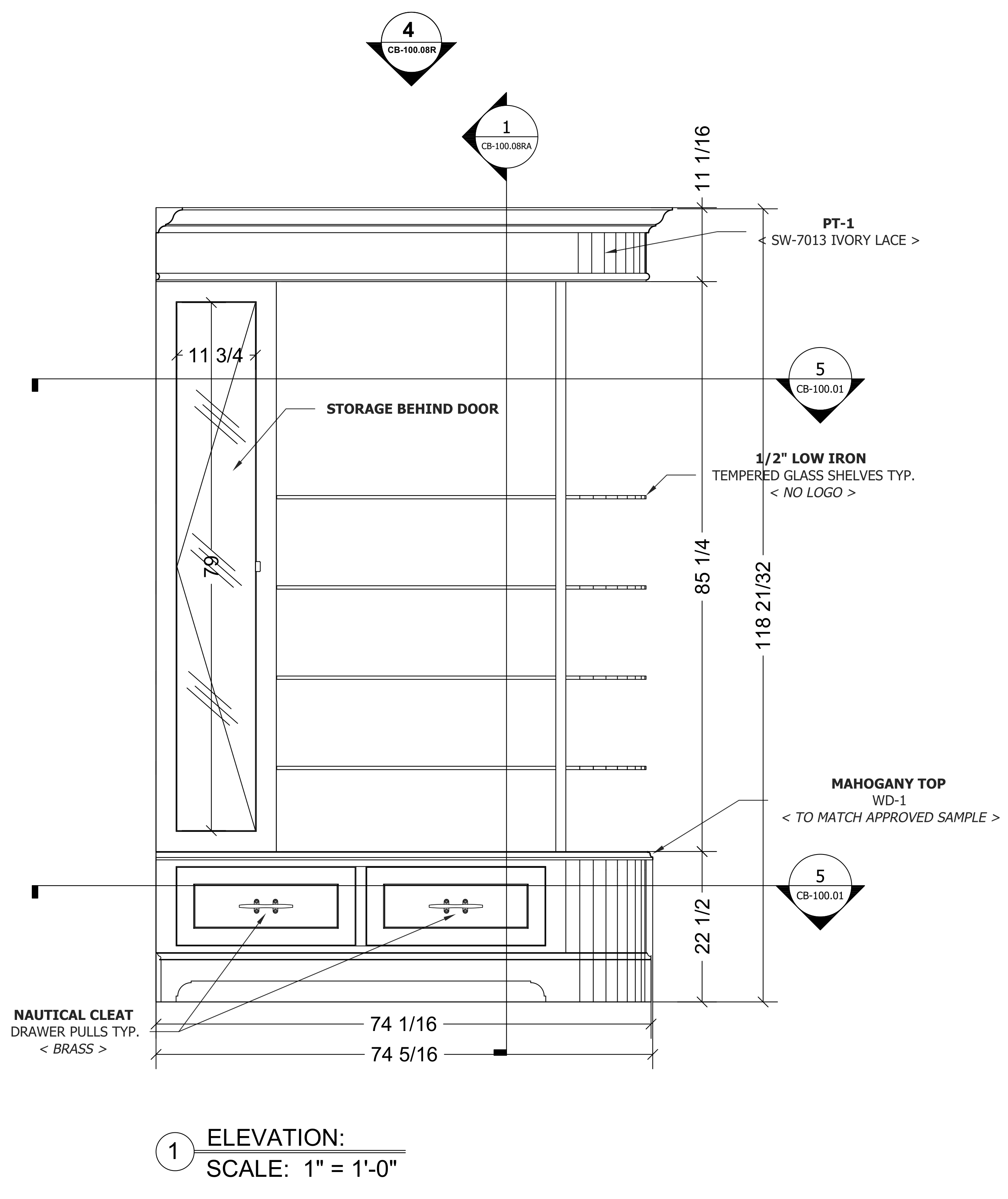
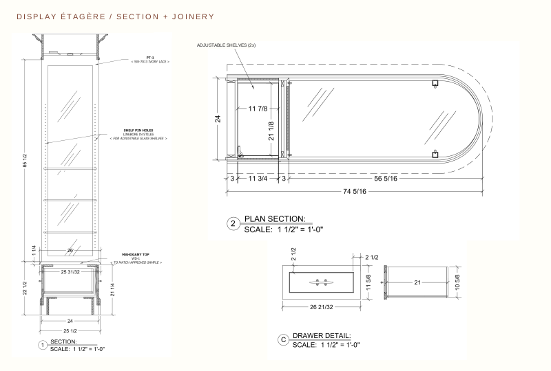
An overall elevation establishes the proportions. Sections and enlarged details resolve shelf supports, curved glazing, drawer construction and finish interfaces—connecting the complete assembly to its individual parts.
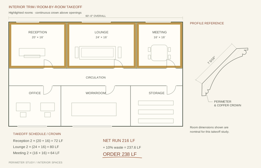
Follow trim room by room, reconcile the dimensions and carry the quantities into a clear schedule. This study highlights three spaces within a larger interior plan, with a separate waste allowance.
Resolve the installation before the parts reach the site. We can build fit allowances, assembly order and specialty hardware requirements into the drawing package so the crew has a clear path from delivery to final adjustment.
Plan scribe zones, shim space and adjustment allowances around field measurements and finish buildup. Define the fit at adjoining surfaces to reduce on-site cutting and rework.
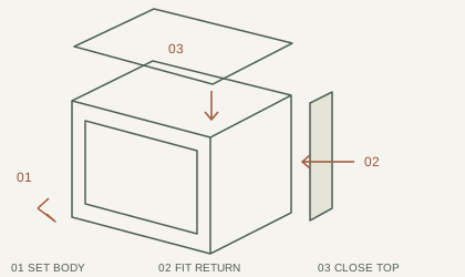
Sequence parts around critical installation clearances, delivery routes and tool access. Identify what must go in first, what stays removable and which trade needs access before closure.
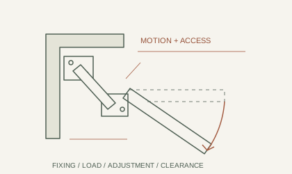
Source and specify specialty hinges, slides, concealed supports and access hardware for challenging conditions. Coordinate loads, mounting details, adjustment and service access with manufacturer requirements.
Illustrative coordination studies. Project allowances and hardware are resolved for the actual assembly and site conditions.
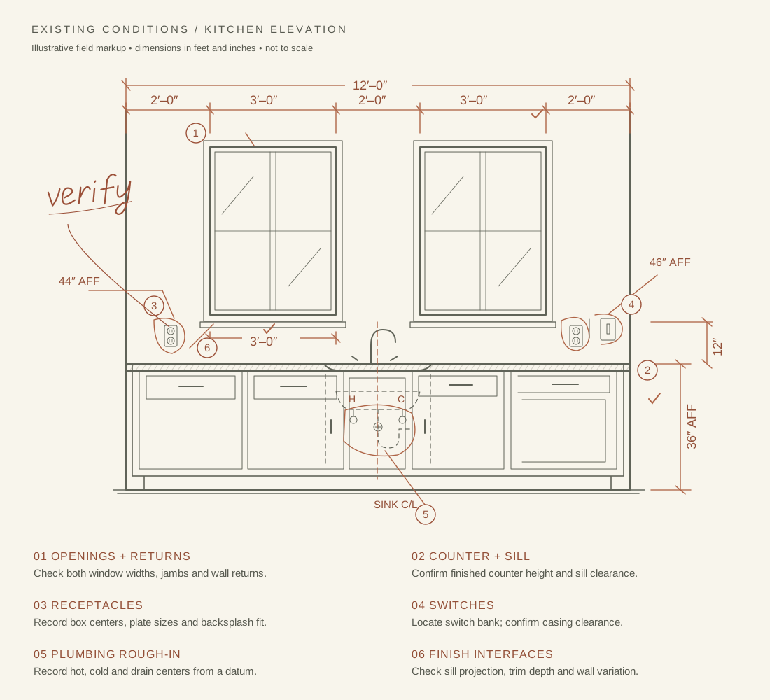
Window openings, counter heights, receptacles, switches and plumbing rough-ins all affect the finished installation. Capture the measurements, mark the conflicts and carry verified site information into the drawing set. Site visits are scoped by location, access and schedule.
We’ll scope the work from there.